Specify the height of the helix. Ad Join millions of learners from around the world already learning on Udemy.

Basic Tutorial Designing A Helical Gear Youtube
Make a circle of 35mm radius at center.

. The pitch circle is the radius which is equal to the distance from the gear axis to the pitch point. Draw a vertical centre line for the driver gear on the left. 02 - create a block of one of the teeth butting onto the circle.
Be sure to check out the Gear Down For What YouTube channel and on thingiverse - he is doing some amazing things with Helical Gears. Df DIN DR ANSI Root diameter. Df dt 2 x m - 2 hfp mn.
The primitif diameter of the gear is much bigger than the 31mm circle. Y position. Specify the center point for the base of the helix.
How do you draw meshing gears. Dt z mn cos beta. Enter flex angleHelix angle as 20degree.
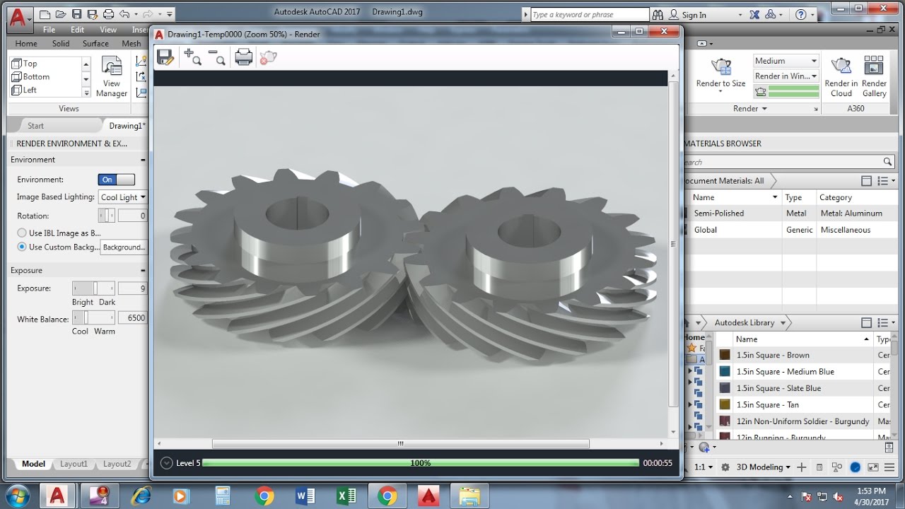
We have the Helical gear created. In either case the gear drawing is indispensible. Normal Circular Thickness on Standard Pitch Circle.
Right click on the screen and select multiple. Download CAD block in DWG. Shift Enter.
This will automaitcally create the teeth for you around the circle you originally created. Helical Pier Cad Drawings for AB Chance. Can I get help.
How to draw 2D helical gear drawing in Autocadshock. Make two arcs like this one for cutting teeth. Then click on the Helix command as in the red box.
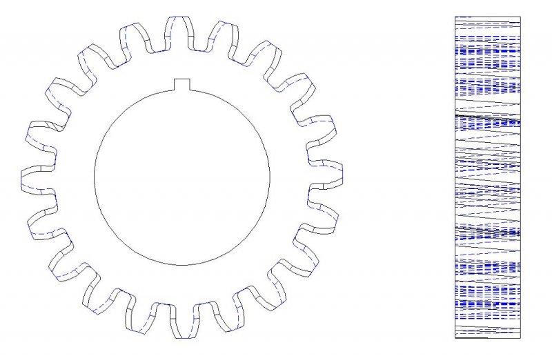
02618 If anyone can help that will be. Number of teeth N. Make the profile of the gear tooth spaces.
We need to compute the following information. Now enter bo command. How do you make a helical gear in AutoCAD.
This command is going to be used for creating the polyline. Make two arcs like this one for cutting teeth. To draw spirals in Autocad click on the Draw pop-up menu as shown by the red arrow above.
Now enter PEDIT command. 16 Diametral Pitch P 20 Tooth N 14-12 Pressure Angle PA involute spur gear. Here is the Dimensions.
Auto position. Right click on the screen and select multiple. Pitch diameter D.
PDF DWG DXF formats for typical piles. Subtract the arrayed sweeps from the cylindrical body and we have the helical gear created. Make a circle of 35mm radius at center.
Although this applies to machine elements in general gear drawings must contain accurate descriptions of principle gear specifications such as number of teeth pitch such as modules pitch circle diameter PCD helix angle of helical teeth value of tooth profile shifting precision grade. Hand of Helix Right or Left E. If you need any tutorial to improve your skill in autocad please visit other tutorial on this blog.
Just to be clear you want to draw a helical gear in 2D and not an involute gear. Specify the starting radius of your spiral in Autocad. Trim down the circles.
It will show the boundary creation dialogue. Gear properties. Start by drawing a horizontal centre line for both gears.
Now the tutorial How to Making a helical gear in AutoCAD has been finished. Change the extrusion height and make it thicker. Trim the circles side ways.
Description See Below Nomenclature. Diameter of the root circle. Specify the top radius or press Enter to specify the same value as the base radius.
Tutorial Making a helical gear in AutoCAD. After entering into the Helix command click to define the center point of your spiral as shown by the red arrow. Enter the triad angle for x axis as 90degree.
This is an easy tutorial on how to model a Helical Gear using AUTOCAD by using SWEEP COMMANDHelicalGearAutocadMechanicalAC3dCADThe Unit for this drawing. Trim down the circles. The easiest way to teach is to demonstrate so here are our parameters for drawing a.
Make a gear module 1mm with 31 teeth and draw on it a circle of 31mm diameter. SS5 SS150 SS175 RS2875203 RS2875276 RS3500300 Brackets Micropile. Autocad scheme is a technical drawing file softare - autocad and gives reference to splice lines geometric constructions among other 1747 KB.
How do you draw a helical gear. 01 - to draw the circle of your gear. How do you make cardboard gears.
Df - dt 2 x mn - 2 hfp mn. 03 - divide the circle by this block by the number of teeth you require. Click Home tab Draw panel Helix.
Maximum Tooth to Tooth Total Error. I have details on a gear but I never drew one before. Make another circle of 50mm concentric to previous one.
Choose flex type Twisting and select the gear body as flex input. Calculate the pitch centre distance. Specify the base radius.
But lets try something new. We can also use PEDIT command. Normal Diametral Pitch or Module.
A scientific calculator is handy for figuring out the cosine of the pressure angle. Make another circle of 50mm concentric to previous one. AutoCAD Item.
Making 3d Helical Gear By Sweep Twist Command Autocad 2017 Youtube
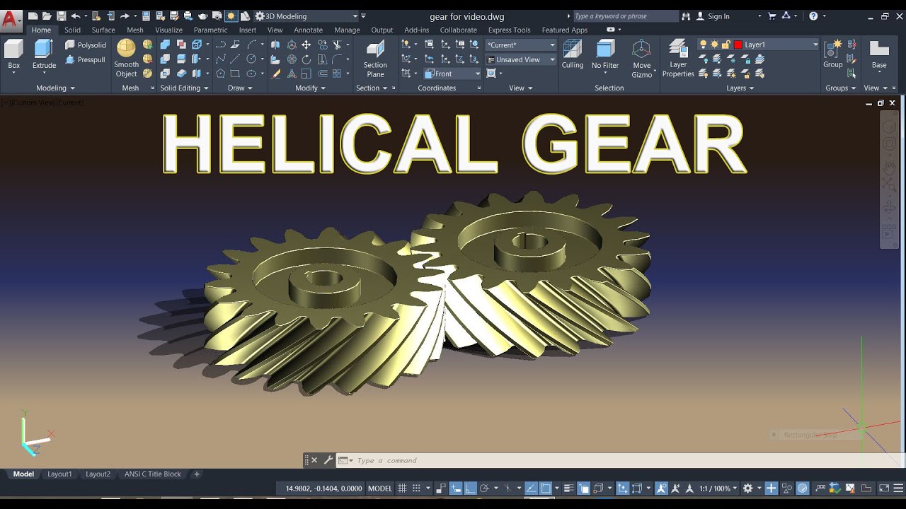
Helical Gear Autocad Design In English Youtube
Making Helical Bevel Gear In Autocad Autocad 3d Modeling Practice 3d Cad Model Library Grabcad

Tutorial Making A Helical Gear In Autocad Grabcad Tutorials

Solved Helical Gear In Inventor Autodesk Community
Helical Gear Student Project Questions Autocad Forums

Making 3d Helical Gear In Autocad Youtube

Autocad 3d Modeling Tutorial How To Make Helical Gear In Autocad 2017 Youtube
0 comments
Post a Comment